“(SKU:RB-01C030)CarDuino Leonardo”的版本间的差异
| 第166行: | 第166行: | ||
} | } | ||
</pre> | </pre> | ||
| + | ==产品相关推荐== | ||
| + | 购买地址:[http://www.alsrobot.cn/goods-114.html Carduino Leonardo 莱昂纳多控制器] | ||
2015年6月4日 (四) 11:08的版本
目录 |
产品介绍
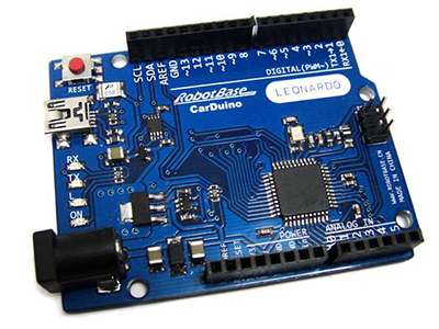
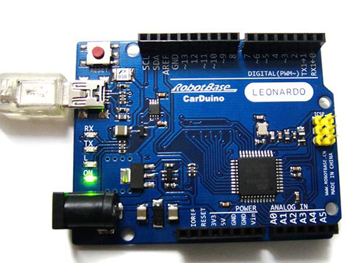
- Carduino Leonardo是一块完全兼容Arduino Leonardo的基于开放源代码的USB接口Simple I/O接口板(包括22通道数字GPIO,7通道PWM输出,12通道10bit ADC输入通道),并且具有使用类似Java、C语言的IDE集成开发环境。让您可以快速使用Arduino语言与Flash或Processing等软件,作出互动作品。
Carduino可以使用开发完成的电子元件例如Switch或sensors或其他控制器、LED、步进马达或其他输出装置。也可作为键盘、鼠标等输入装置。Carduino Leonardo也可以独立运作成为一个可以跟软件沟的接口,例如说:Flash Processing Max/MSP VVVV 或其他互动软件。Arduino开发IDE接口基于开放源代码,可以让您免费下载使用开发出更多令人惊艳的互动作品。
Arduino基本技术参数
1. 控制器: ATmega32u4
2. 工作频率: 16 MHz
3. 工作电压: 5V
4. 输入电压(推荐): 7-12V
5. 数字IO口: 22 (D0~D13,D14-MISO,D15-SCK,D16-MOSI,D18~23[A0~A5])
6. PWM通道: 7(D3,D5,D6,D9,D10,D11,D13)
7. 模拟输入: 12(A0~A5,D4-A6,D6-A7,D8-A8,D9-A9,D10-A10,D12-A11)
8. 5V数字/模拟口最大允许电流: 40 mA
9. 3.3V 数字/模拟口最大允许电流: 50 mA
10. Flash Memory: 32 KB (ATmega32u4) of which 4 KB used by bootloader
11. SRAM: 2.5 KB (ATmega32u4)
12. EEPROM: 1 KB (ATmega32u4)
Arduino下载软件及开发环境
1,软件下载
请下载arduino1.01或以上版本
官方软件下载地址:http://arduino.cc/en/Main/Software
2,软件及硬件驱动安装
此软件是绿色版,软件解压缩后即可使用。
解压软件下载地址:
http://jaist.dl.sourceforge.net/project/sevenzip/7-Zip/9.20/7z920.exe
软件解压完成后,接下来要安装CrduinoLeonardo硬件驱动。
将Crduino Leonardo上的方头MiNi USB连接好之后,另外一端的USB连接到计算机任意一个USB接口。
接下来系统就会出现Arduino Leonardo的Windows Update驱动程序安装画面。
不过目前在Windows Update中还无法找到驱动程序。
这时需要我们手动安装驱动,打开“控制面板”下的“设备管理器”
这时在其他设备里会出现一个带有叹号的Arduino Leonardo设备。在上图标上点击右键选择“更新驱动程序软件”
在“您想如何搜索驱动程序软件”中选择“浏览计算机以查找驱动程序软件”
然后选择你Arduino IDE软件解压到盘符找到Drivers文件夹点击下一步
这时会出现Windows无法验证此驱动程序软件发布者警告
安装完成后在“端口(COM和LPT)”下回生成一个新的端口我这里生成的是COM3
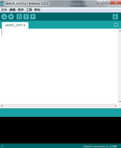
3,Arduino编译下载软件使用说明 打开软件只需双击执行arduino.exe执行文件,就可以看到如下程序编译窗口。从Arduino1.0开始已经支持中文界面了。具体修改方法电机“文件”-“参数设置”下。
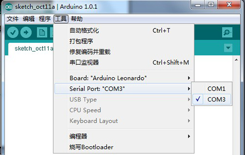
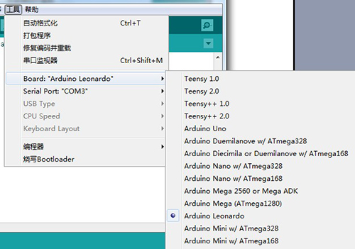
在输入程序前需要先选择板号和COM口,COM口号就是我们刚才驱动上的COM3。在“工具”-“Serial Port”下选择。
然后选择版型位置在“工具”-“Board:”-“Arduino Leonardo”。
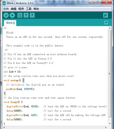
基本设置完毕就可以编写程序了。首先我们打开一个闪灯的例程。位置在“文件”-“示例”-“01.Basic”-“Blink”。
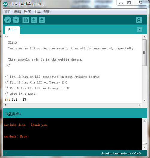
点击(图)可以将程序进行编译,检查是否有语法错误。点击(图)可以将程序下载到CarduinoLeonardo中。下载成功会在状态窗格显示“下载完毕”
这时会发现Carduino Leonardo一秒亮灭交替闪烁。
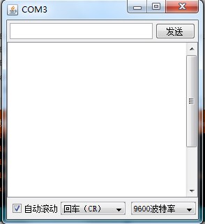
若需要进行与Arduino串口通信点击通信监视窗口(图),可以看到如下对话框。
Arduino基本语言概述
Arduino使用起来要比其他微处理器更易懂,与Basic Stamp有些相似,Arduino的编程语言更为简单和人性化,Arduino编程语言基于C语言,但其实用性要远高于C语言,主要由于它将一些常用语句组合函数化,例如:延时函数delay(1000)即为一秒。
Arduino程序基本架构
(1)声明变量及接口名称(int val; int ledPin=13;)。
(2)setup()——函数在程序开始时使用,可以初始化变量、接口模式、启用库等(例如:pinMode(ledPin,OUTUPT);)。
(3)loop()——在setup()函数之后,即初始化之后,loop() 让你的程序循环地被执行,使用它来运转Arduino。
Arduino常用编程语言
(1)pinMode(接口名称,OUTPUT或INPUT)将——接口定义为输入或输出接口,用在setup()函数里。
(2)digitalWrite(接口名称,HIGH或LOW)——将数字接口值至高或低。
(3)digitalRead(接口名称)——读出数字接口的值。
(4)analogWrite(接口名称, 数值)——给一个接口写入模拟值(PWM波)。对于ATmega168芯片的Arduino(包括Mini或BT),该函数可以工作于 3,5,6,9,10和 11号接口。老版的 ATmega8芯片的USB和 serial Arduino仅仅支持 9,10和11号接口。
(5)analogRead(接口名称)——从指定的模拟接口读取值,Arduino对该模拟值进行10-bit的数字转换,这个方法将输入的0-5电压值转换为 0到1023间的整数值。
(6)delay()——延时一段时间,delay(1000)为一秒。
(7)Serial.begin(波特率)——设置串行每秒传输数据的速率(波特率)。在同计算机通讯时,使用下面这些值:300,1200,2400,4800,9600,14400,19200,28800,38400,57600或 115200。你也可以在任何时候使用其它的值,比如,与0号或1号插口通信就要求特殊的波特率。用在setup()函数里
(8)Serial.read()——读取持续输入的数据。
(9)Serial.print(数据,数据的进制)——从串行端口输出数据。Serial.print(数据)默认为十进制等于Serial.print(数据,DEC)。
(10)Serial.println(数据,数据的进制)——从串行端口输出数据,跟随一个回车和一个换行符。这个函数所取得的值与 Serial.print()一样。
使用Carduino Leonardo鼠标应用
1、需要的器材:
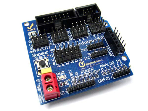
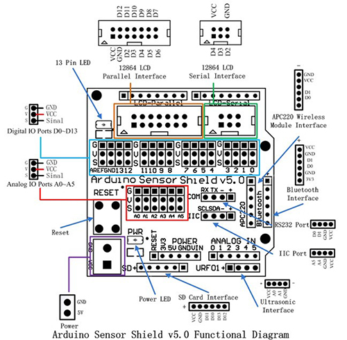
1) Arduino传感器扩展板
接口示意图如下:
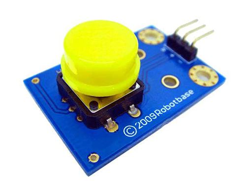
2)按压式大按钮模块
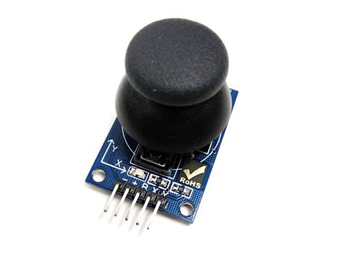
3)双轴按键摇杆
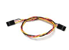
4) 3PIN传感器连接线
两条3PIN传感器连接线
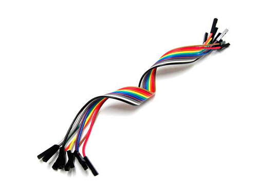
5)杜邦线
两条杜邦线
2,硬件连接:
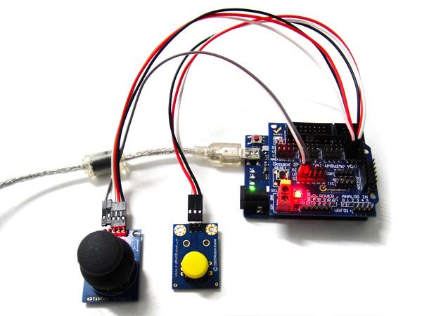
将传感器扩展板插到Carduino Leonardo上,用3PIN数据线将按键接到数字2口上作为启动和关闭鼠标的功能键,将Joystick上B(Button)接到数字3口上,X(X轴)接到模拟0口,Y(Y轴)接到模拟1口。
3,例程源代码:
const int switchPin = 2; // switch to turn on and off mouse control
const int mouseButton = 3; // input pin for the mouse pushButton
const int xAxis = A0; // joystick X axis
const int yAxis = A1; // joystick Y axis
const int ledPin = 5; // Mouse control LED
// parameters for reading the joystick:
int range = 12; // output range of X or Y movement
int responseDelay = 5; // response delay of the mouse, in ms
int threshold = range/4; // resting threshold
int center = range/2; // resting position value
boolean mouseIsActive = false; // whether or not to control the mouse
int lastSwitchState = LOW; // previous switch state
void setup() {
pinMode(switchPin, INPUT); // the switch pin
pinMode(ledPin, OUTPUT); // the LED pin
// take control of the mouse:
Mouse.begin();
}
void loop() {
// read the switch:
int switchState = digitalRead(switchPin);
// if it's changed and it's high, toggle the mouse state:
if (switchState != lastSwitchState) {
if (switchState == HIGH) {
mouseIsActive = !mouseIsActive;
// turn on LED to indicate mouse state:
digitalWrite(ledPin, mouseIsActive);
}
}
lastSwitchState = switchState;// save switch state for next comparison:
// read and scale the two axes:
int xReading = readAxis(A0);
int yReading = readAxis(A1);
// if the mouse control state is active, move the mouse:
if (mouseIsActive) {
Mouse.move(xReading, yReading, 0);
}
// read the mouse button and click or not click:
// if the mouse button is pressed:
if (digitalRead(mouseButton) == HIGH) {
// if the mouse is not pressed, press it:
if (!Mouse.isPressed(MOUSE_LEFT)) {
Mouse.press(MOUSE_LEFT);
}
}
// else the mouse button is not pressed:
else {
// if the mouse is pressed, release it:
if (Mouse.isPressed(MOUSE_LEFT)) {
Mouse.release(MOUSE_LEFT);
}
}
delay(responseDelay);
}
int readAxis(int thisAxis) {
// read the analog input:
int reading = analogRead(thisAxis);
// map the reading from the analog input range to the output range:
reading = map(reading, 0, 1023, 0, range);
// if the output reading is outside from the
// rest position threshold, use it:
int distance = reading - center;
if (abs(distance) < threshold) {
distance = 0;
}
return distance;// return the distance for this axis
}
